Here you will learn about the processes involved with taking the device apart without causing damage. Keep in mind that we will be working with sensitive electronic components, if you aren't comfortable opening up the device and potentially causing damage DO NOT PROCEED! Ask someone who is able and willing to help you, show them this guide, and prepare to blame them if something goes wrong. I take no responsibility for your actions if you cause damage to your device. PROCEED AT YOUR OWN RISK. Now that we have all of that out of the way, make sure you have all of the required tools and any other helpful tools and supplies so that we can begin!
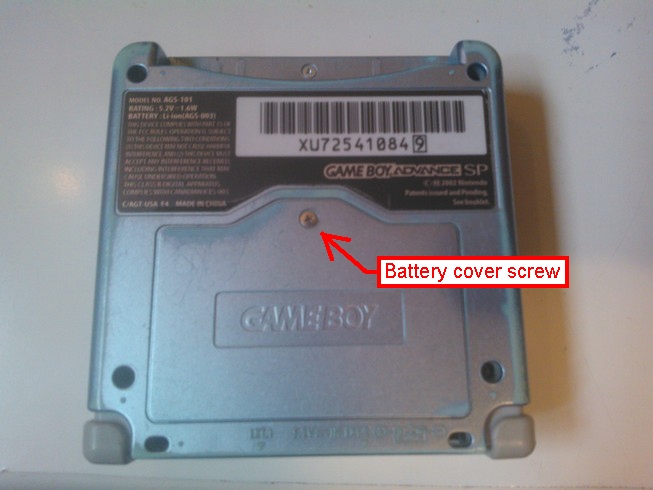
We start by removing the battery. Take your Phillips 00 and remove the battery panel on the bottom of the device
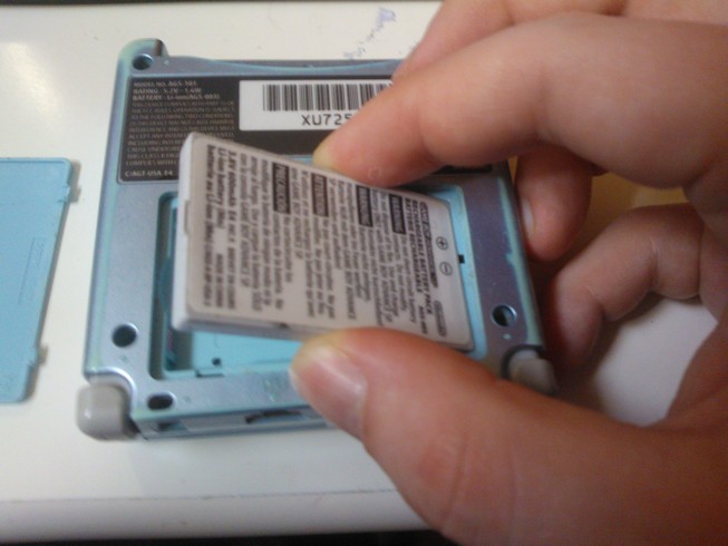
With the panel removed, lift the battery by the small notch. The battery will lift out of the device at an angle.
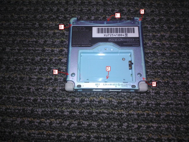
Next, we need to remove the 6 tri winged screws, so take out your tri wing screwdriver and remove the screws in the following order.
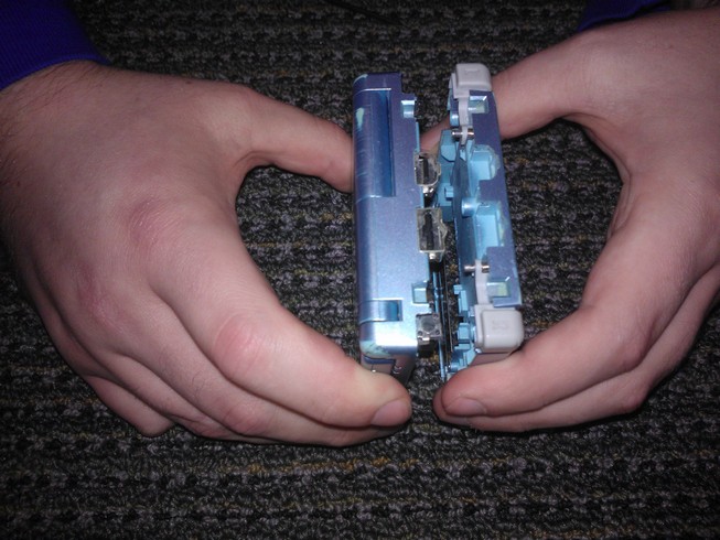
Now carefully separate the bottom case from the rest of the device, it should lift off without any resistance. In the image I show removing the case at an angle but it doesn't really matter.
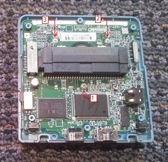
Locate the three screws around the center of the main board and remove them in a counter-clockwise manner.
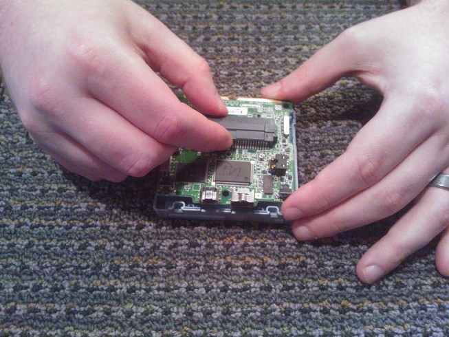
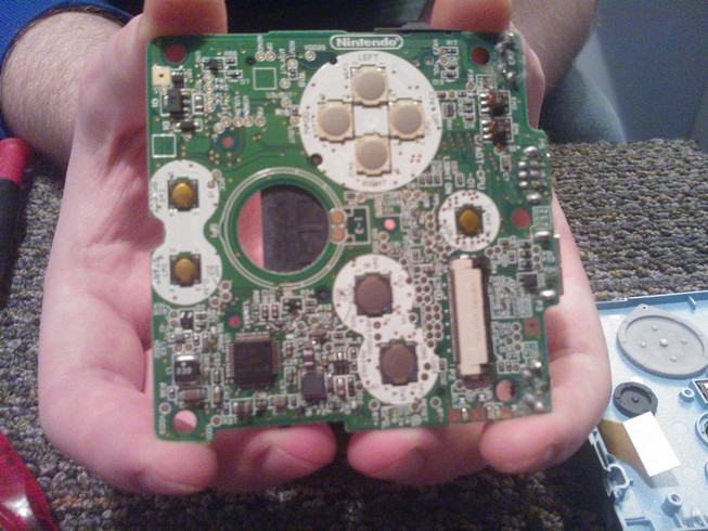
Next, carefully remove the board by first holding on to the cartridge port and then grabbing the board by the edges. Remember to always hold the board by the edges, touching any other part of the board can cause permanent damage through electro static discharge or ESD. DO NOT PULL ON THE BOARD!! As the next step will show, there is a ribbon cable attached to the underside of the board.
Locate the ribbon cable and lay the board down revealing the connector on the board that holds the ribbon cable.
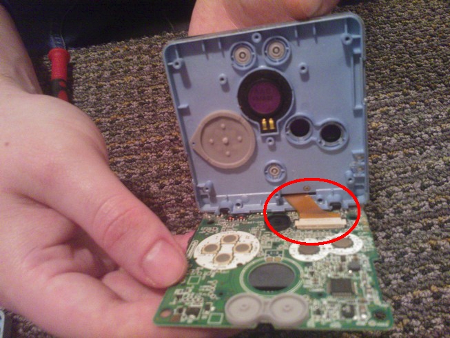
Use a screwdriver or a spudger to carefully push the black pegs on the left and right edges of the connector on the board toward the direction of the cable.
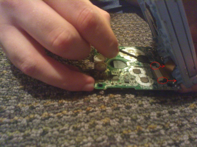
This will allow you to completely remove the board from the device for cleaning or replacement. See the supplies section of the FAQ page for advice on cleaning supplies.
When removing the board, sometimes the silicon covers to the buttons will stick to the board causing the buttons to fall out. This is fine because the buttons can only be installed the correct way due to notches around the buttons.
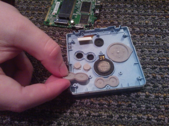
The silicon covers should come off easily, but will probably be quite dirty so get out those cotton swabs and start cleaning or replace these parts if needed.
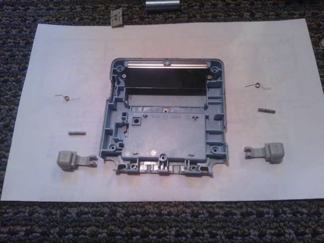
The remaining buttons and switches can be found on the bottom case that we removed earlier. First we'll take a look at the power switch. This switch should lift directly up out of the case without any resistance.
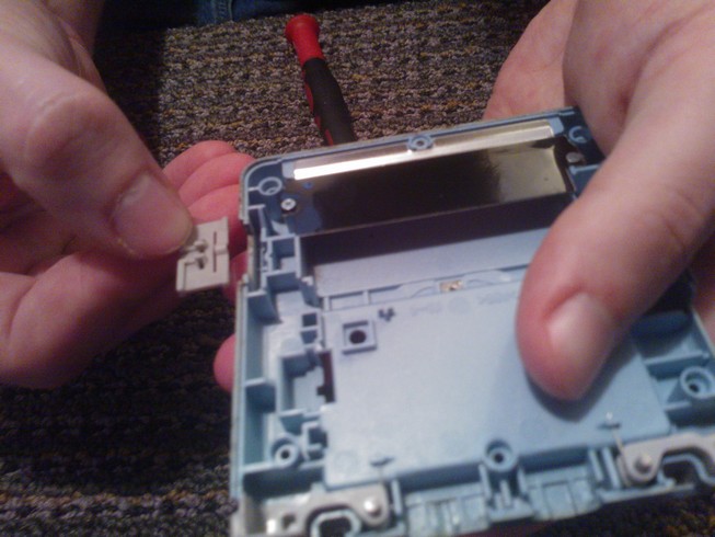
Next we'll check out the shoulder buttons L and R. Each button is made up of three parts, the plastic button itself, a specially formed spring, and a small metal bar that holds it all together and fits into a hole on the bottom case. To remove, carefully lift the button and metal bar up out of the case taking care to not lose the spring.
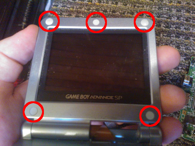
Now we need to remove the five pads that are glued to the screws in the bezel of the screen. I've found that a pointy knife is the best tool for this task, but take care not to accidentally scratch the plastic case.
With the pads removed, unscrew the five screws and close the clamshell. The top part of the case behind the screen should lift off without any effort now, revealing the back side of the screen.
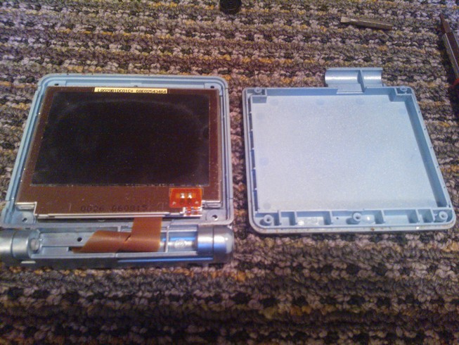
Carefully feed the ribbon cable through the case and we will have successfully separated the screen from the device. A replacement might not have the ribbon cable twisted like the existing cable is, so take note of how it's twisted if you're replacing it.

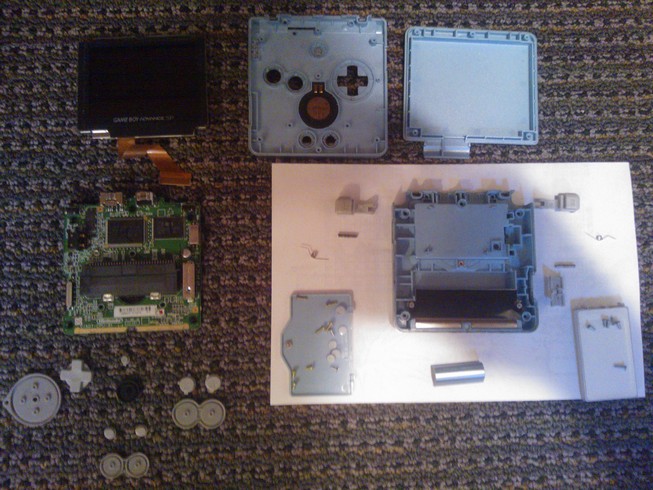
And that's it! We have completely disassembled the device!